I got asked to do a composite video modification (mod) on an Atari 2600 games console from the 80’s recently. The Atari 2600 has a built in RF-modulator that produces a very bad signal on modern TV’s, and it is not possible to connect it to a monitor without RF-input where you “tune” in to channels 2 or 3.
NOTE: I did not “invent” this modification. Although I understand the concept behind it, I have researched info found in the big Internet 🙂
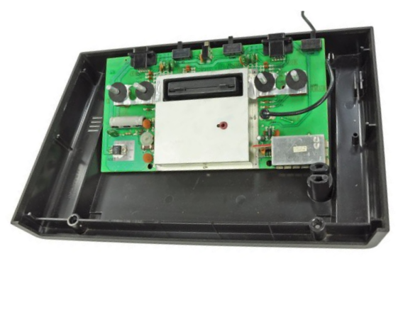
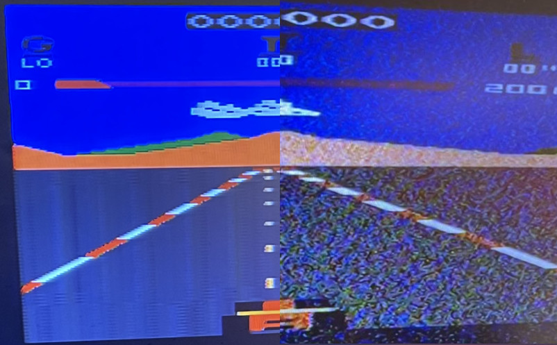
This is how the image on my modern LCD-TV looked like from the Atari using the RF-signal:

However, the Atari is producing a composite video-signal internally which is then converted to RF together with the audio signal via the internal RF-modulator box. It is therefore a pretty simple task to modify the Atari to send the composite signal and audio out of the machine using standard RCA-sockets.
There are several solutions, but this is the simplest one. I have done this solution a couple of times before, and it works very well, but the picture is not perfect. More complicated solutions will produce an even better image.
NOTE: This description is for the PAL version of the old Atari 2600 version with 4 switches on the top

However, the same mod can be used on the other variants (6-switch and jr version), but then there will be a slight difference in how you connect the mod circuit and how you modify the board.
Get started
Open up the machine. There is only 4 screws under the console. Then take of the top cover.
Remove the RF-cable. You will not need it anymore.
Open the metal case by twisting the tab’s and pulling the box up. Remove also the metal case on the back-side if you want to inspect and clean it, and also if you want to de-solder some components that will be removed later.
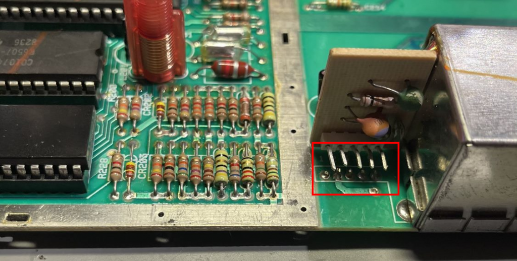
Then cut or de-solder the pins for the RF-modulator as shown in red. Here they are cut, but I later removed the left-over pins from the board. You can also de-solder and remove the whole RF-modulator box if you want to, or you can just leave it in place, it will not be used.
Then you need to remove some components. You can just cut them of or de-solder them completely to leave a more clean board.
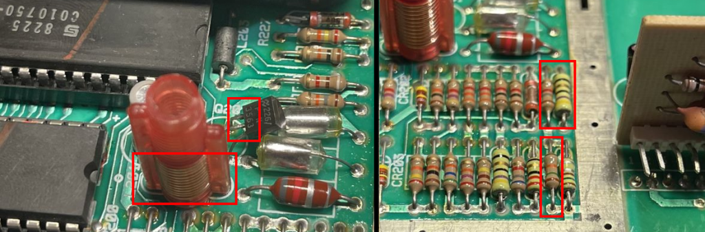
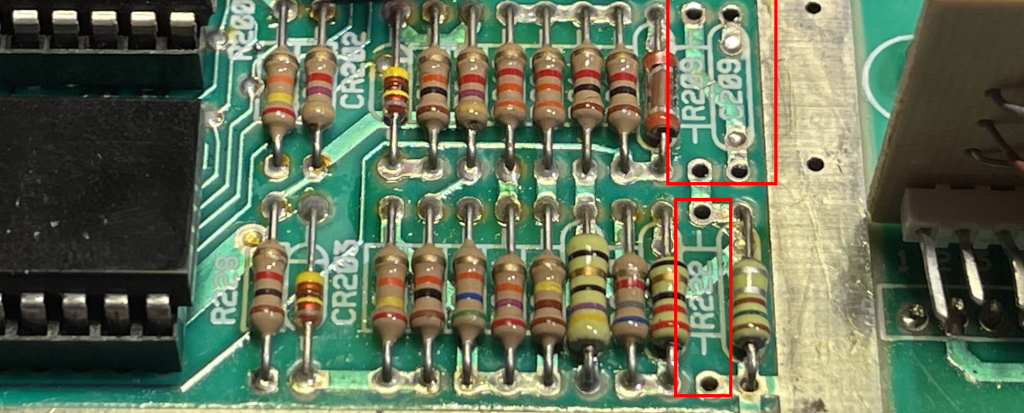
Locate the transistor and the inductor that is next to the IC’s and remove both. Then find capacitor C209 and C205 and resistor R222 and remove or cut those as well.
Make the mod circuit
The circuit is very simple and consists of just one transistor and two resistors
- 2N 3904 Transistor
- 2200 ohms resistor (2K2)
- 3300 ohms resistor (3K3)
- Some wires
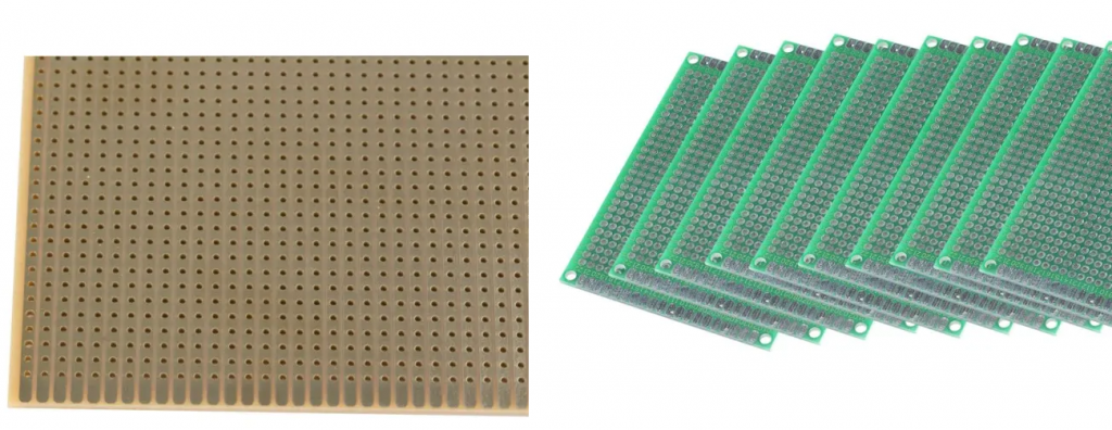
To make this circuit you can just solder the legs of the components to each others and the wires, but it is better to use a perf board or experiment board like these:
Connect the components and the wires like this:
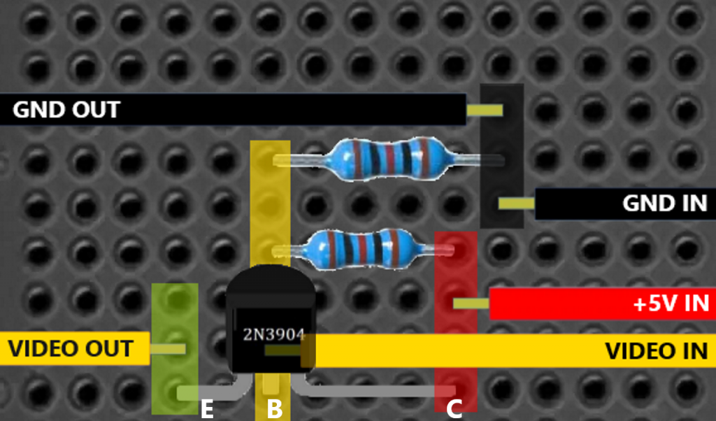
NOTE the direction of the transistor and the emitter (E), base (B) and collector (C)
The transparent colors indicate what to connect (and bridge with solder), and the wires shows the different input and output signals. Each wire should be at least 25 cm long (you cut them to length after).
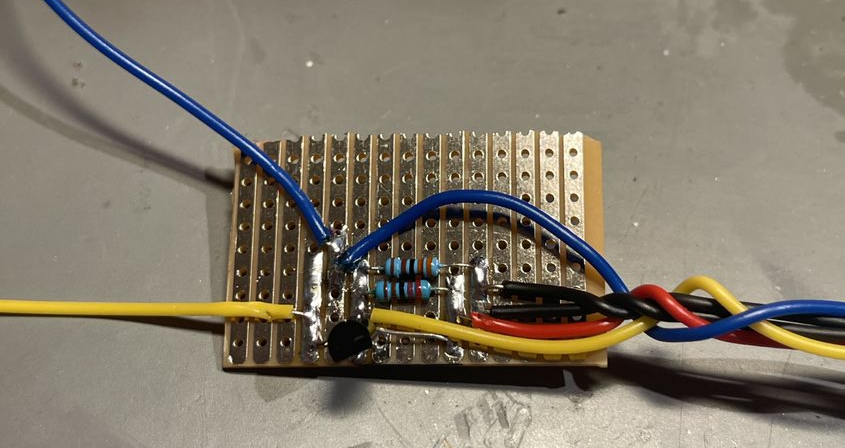
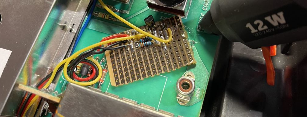
After soldering up the circuit it should look something like this:
Connecting the mod to the Atari
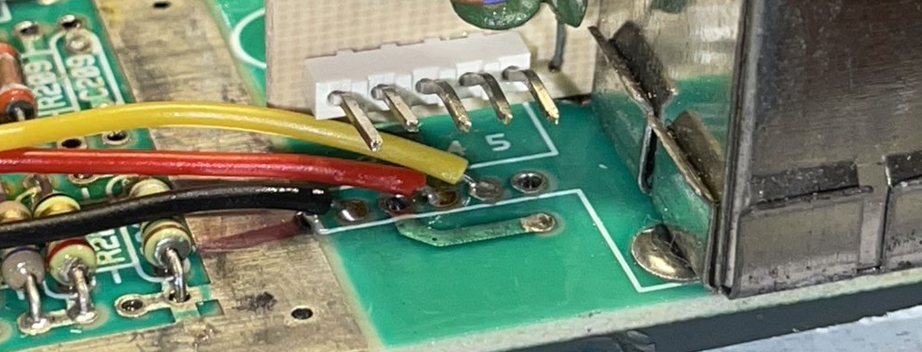
To connect the mod board to the Atari, you solder the input wires to the output pins that the RF-modulator was soldered to. There are 5 connectors, but only 3 are used.
- Black GND input wire goes to pin 1
- Red +5V input goes to pin 3
- Yellow Video signal input goes to pin 4
Cut the wires to a length where they fit with where you want to place the mod board. Strip of the ends and solder them to the board through the holes in the board.
NOTE: If you removed the RF-modulator, it will be a good idea to place the mod board where the RF-modulator were. I did not remove the modulator as I always want mods to be reversible.
Solder a wire for the audio to the resistor next to the ones you removed as seen in this image:
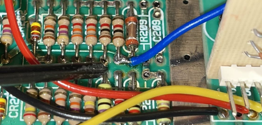
The audio-wire should go directly to the audio output RCA-contacts, and it should be around 25 cm long (adjust length later).
Find a good spot on the Atari motherboard to place the composite mod board. Or if you plan to place it outside the board in the plastic case, make sure you have long enough wires.
I placed it next to the RF modulator. Make sure that no bare wires or component leads are touching any wires or components on the motherboard electrically. I used hot-glue under the mod board to fix it to the motherboard with 2 mm clearance.
Now you can put back the metal case over the motherboard. Feed the audio-wire (blue) out under the metal. Feed the other input wires between the metal case and the RF modulator.
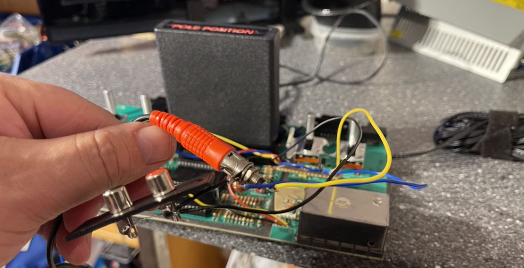
It’s a good idea to test that the mod works before you glue the board to the console and start adding the RCA-contacts to the console etc.
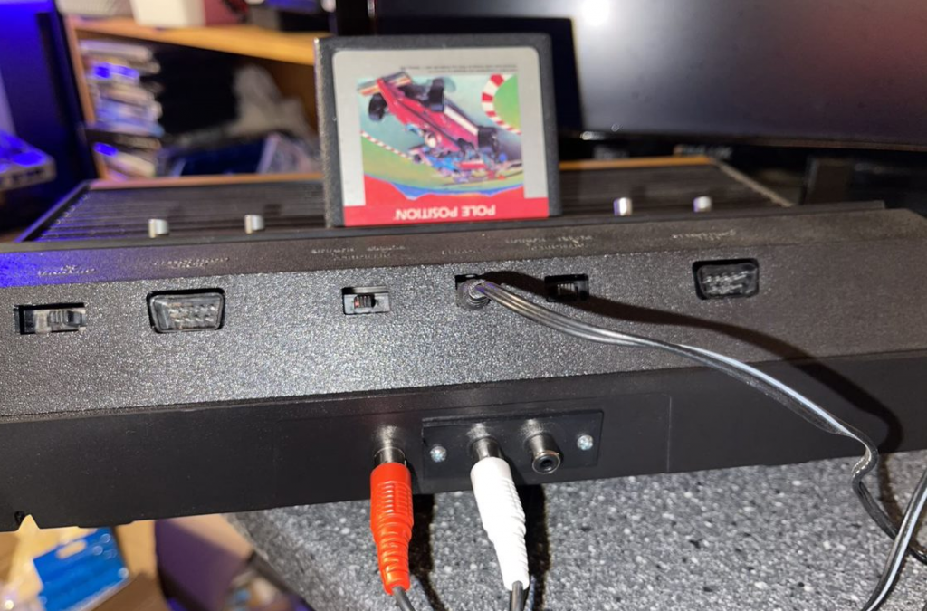
Adding the RCA contacts
Add 3 female RCA-connectors to the back of the bottom part of the case (or wherever you want them). The type you can solder wires to. Drill 6 mm holes in the case for the connectors. Make sure to have enough space between the connectors to be able to plug in the contacts as they can be wider. Preferable one black, one red and one yellow (for the video).
I used a panel with two RCA-connectors for the audio and one single black for the video (this is what I had). I used my Dremel to cut out a rectangle for the panel, then drilled a 6 mm hole for the other one.
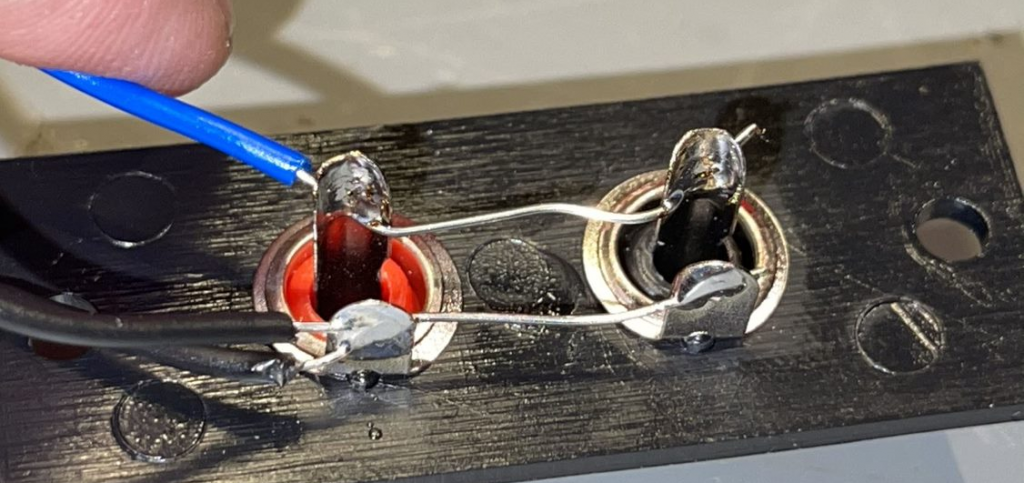
Solder a short wire between both audio connectors center pin (the Atari has only mono audio) to get the same audio signal on both connectors. Solder a wire between all 3 connectors ground (outer solder pins). This can be done before you insert the contacts in the case.
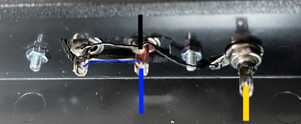
- Solder the blue audio wire to the audio connectors center pin.
- Solder the black ground wire to the ground pin on one of the connectors.
- Solder the yellow video wire to the center pin of the video connector.
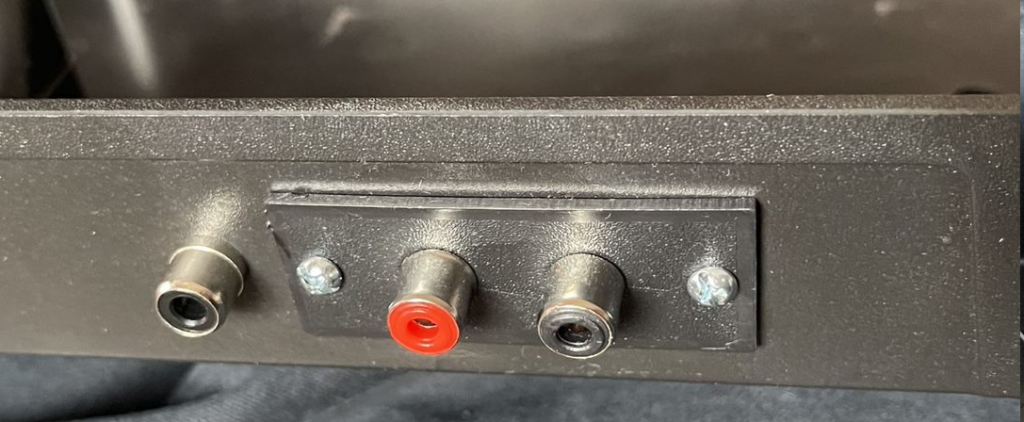
This is the result after screwing the contacts in to the case:
Finally, you should use glue on the wires to make sure they don’t move to much inside the console.

Conclusion
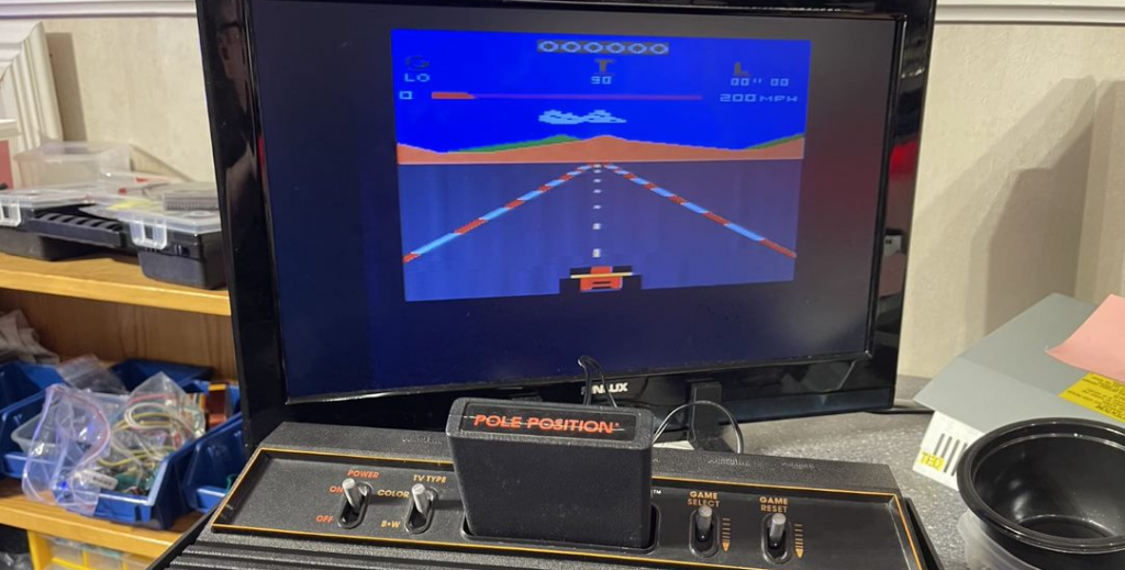
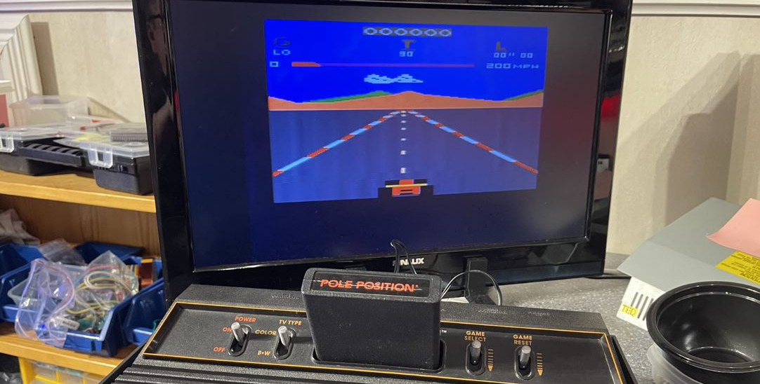
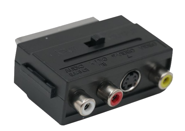
If you did everything correctly you can now connect the Atari to a modern TV or monitor with the RCA-contacts. You need a RCA-cable for that. You can also use a SCART-adapter if you prefer or your TV only have SCART input, or even a HDMI upscaler device to get HDMI output.
Now the picture quality should have improved a lot. You will probably still see some shadows or artefacts, but it is a great improvement from the RF-signal
Play on!